INTRODUCTION
So far we have limited our study to resistive circuits. In this chapter, we shall introduce two new and important passive linear circuit elements: the capacitor and the inductor. Unlike resistors, which dissipate energy, capacitors and inductors do not dissipate but store energy, which can be retrieved at a later time. For this reason, capacitors and inductors are called storage elements.
The application of resistive circuits is quite limited. With the introduction of capacitors and inductors in this chapter, we will be able analyze more important and practical circuits. Be assured that the circuit analysis techniques covered in chapters 3 and 4 are equally applicable to circuits with capacitors and inductors.
We begin by introducing capacitors and describing how to combine them in series or in parallel. Later, we do the same for inductors. As typical applications, we explore how capacitors are combined with op amp to form integrators, differentiators.
CAPACITORS
A capacitor is a passive element designed to store energy in its electric field. Besides resistors, capacitors are the most common components. Capacitors are used extensively in electronics, communications, computers, and power systems. For example, they are used in the tuning circuits of radio receivers and as dynamic memory elements in computer systems.
A capacitor is typically constructed as depicted in [link].
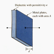
A capacitor consists of two conducting plates separated by an insulator (or dielectric).
In many practical applications, the plates may be aluminum foil while the dielectric may be air, ceramic, paper, or mica.
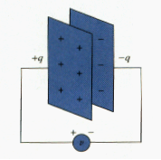
When a voltage source v is connected to the capacitor, as in [link], the source deposits a positive charge q on one plate and a negative charge – q on the other. The capacitor is said to store the electric charge. The amount of charge stored, represented by q, is directly proportional to the applied voltage v so that
Where C, the constant of proportionality, is known as the capacitance of the capacitor. The unit of capacitance is the farad (F) in honor of the English physicist Michael Faraday (1791-1867). From [link], we may derive the following definition.
Capacitance is the ratio of the charge on one plate of a capacitor to the voltage difference between the two plates, measured in farads (F).
Note that from [link] that 1 farad = 1 coulomb/volt.
Although the capacitance C of capacitor is the ratio of the charge q per plate to the applied voltage v, it does not depend on q or v. it depends on the physical dimensions of the capacitor. For example, for the parallel plate capacitor shown in [link], the capacitance is given by
Where A is the surface area of each plate, d is the distance between the plates, and is the permittivity of the dielectric material between the plates. Although [link] applies to only parallel-plate capacitors, we may infer from it that, in general, three factors determine the value of the capacitance:
- The surface area of the plate – the larger the area, the greater the capacitance.
- The spacing between the plates – the smaller the spacing, the greater the capacitance.
- The permittivity of the material – the higher the permittivity, the greater the capacitance.
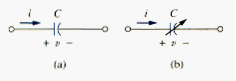
Capacitors are commercially available in different values and types. Typically, capacitors have values in the picofarad (pF) to microfarad ( F) range. They are described by the dielectric material they are made of and by whether they are of fixed or variable type. [link] shows the circuit symbols for fixed and variable capacitors. Note that according to the passive sign convention, current is considered to flow into the positive terminal of the capacitor when the capacitor is being charged, and out of the positive terminal when the capacitor is discharging.
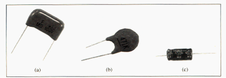
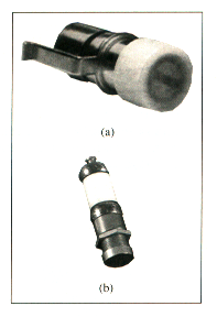
[link] shows common types of fixed-value capacitors. Polyester capacitors are light in weight, stable, and their change with temperature is predictable. Instead of polyester, other dielectric materials such as mica and polystyrene may be used. Film capacitors are rolled and housed in metal or plastic films. Electrolytic capacitors produce very high capacitance.
[link] shows the most common types of variable capacitors. The capacitance of a trimmer (or padder) capacitor or a glass piston capacitor is varied by turning the screw. The trimmer capacitor is often placed in parallel with another capacitor so that the equivalent capacitance can be varied by turning slightly. The capacitance of the variable air capacitor (meshed plate) is varied by turning the shaft. Variable capacitors are used in radio receivers allowing one to tune to various stations. In addition, capacitors are used to block dc, pass ac, shift phase, store energy, start motors, and suppress noise.
To obtain the current-voltage relationship of the capacitor, we take the derivative of both sides of [link]. Since
Differentiating both sides of [link] gives
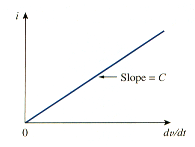
This is current-voltage relationship for a capacitor, assuming the passive sign convention. The relationship is illustrated in [link] for a capacitor whose capacitance is independent of voltage. Capacitors that satisfy [link] are said to be linear. For a nonlinear capacitor, the plot of the current-voltage relationship is not a straight line. We will assume linear capacitors in this book.
The voltage-current relation of the capacitor can be obtained by integrating both sides of [link]. We get
or
where is the voltage across the capacitor at time . [link] shows that capacitor voltage depends on the past history of the capacitor current. Hence, the capacitor has memory – a properly that is often exploited.
The instantaneous power delivered to the capacitor is
The energy stored in the capacitor is therefore
We note that v(-∞) = 0, because the capacitor was uncharged at . Thus,
Using [link], we may rewrite [link] as
[link] or [link] represents the energy stored in the electric field that exists between the plates of the capacitor. This energy can be retrieved, since an ideal capacitor cannot dissipate energy. In fact, the word capacitor is derived from this element’s capacity to store energy in the electric field.
We should note the following important properties of a capacitor:
1. Note from [link] that when the voltage across a capacitor is not changing with time (i.e., dc voltage), the current through the capacitor is zero. Thus,
A capacitor is an open circuit to dc.
However, if a battery (dc voltage) is connected across a capacitor, the capacitor changes.
2. The voltage on the capacitor must be continuous.
The voltage on a capacitor cannot charge abruptly.
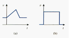
The capacitor resists an abrupt change in the voltage across it. According to [link], a discontinuous change in voltage requires an infinite current, which is physically impossible. For example, the voltage across a capacitor may take the form shown in [link](a), whereas it is not physically possible for the capacitor voltage to take the form shown in [link](b) because of the abrupt changes. Conversely, the current through a capacitor can change instantaneously.
- The ideal capacitor does not dissipate energy. It takes power from the circuit when storing energy in its field and returns previously stored energy when delivering power to the circuit.
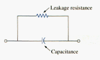
- A real, nonideal capacitor has a parallel-model leakage resistance, as shown in Figure 8. The leakage resistance may be as high as 100 M and can be neglected for most practical applications. For this reason, we will assume ideal capacitors in this book.
SERIES AND PARALELL CAPACITORS
We know from resistive circuit that series-parallel combination is a powerful tool for reducing circuits. This technique can be extended to series-parallel connections of capacitors, which are sometimes encountered. We desire to replace these capacitors by a single equivalent capacitor .
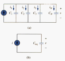
In order to obtain the equivalent capacitor of N capacitors in parallel, consider the circuit in [link](a). The equivalent circuit is in [link](b). Note that the capacitors have the same voltage v across them. Applying KCL to [link](a),
But . Hence,
Where
The equivalent capacitance of N parallel-connected capacitors is the sum of the individual capacitors.
We observe that capacitors in parallel combine in the same manner as resistors in series.
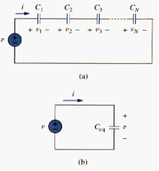
We now obtain of N capacitors connected in series by comparing the circuit in Figure 10(a) with the equivalent circuit in Figure 10(b). Note that the same current i flows (and consequently the same charge) through the capacitors. Applying KVL to the loop in Figure 10(a),
But , therefore,
Where
The initial voltage across is required by KVL to be the sum of the capacitor voltages at . Or according to [link],
Thus, according to [link],
The equivalent capacitor of series connected capacitors is the reciprocal of the sum of the reciprocals of the individual capacitances.
Note that capacitors in series combine in the same manner as resistors in parallel. For N = 2 (i.e., two capacitors in series), [link] becomes
or
INDUCTORS
An inductor is a passive element designed to store energy in its magnetic field. Inductors find numerous applications in electronic and power systems. They are used in power supplies, transformers, radios, TVs, radars and electric motors.
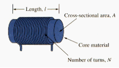
Any conductor of electric current has inductive properties and be regard as an inductor. But in order to enhance the inductive effect, a practical inductor is usually formed into a cylindrical coil with many turn of conducting wire, as shown in [link].
An inductor consists of a coil of conducting wire.
If current is allowed to pass through an inductor, it is found that the voltage across the inductor is directly proportional to the time rate of change of current. Using the passive sign convention,
Where L is the constant of proportionality called the inductance of the inductor. The unit of inductance is the Henry (H), named in honor of the American inventor Joseph Henry (1797-1878). It is clear from [link] that 1 Henry equals 1 volt-second per ampere.
Inductance is the property whereby an inductor exhibits opposition to the charge of current flowing through it, measured in Henry (H).
The inductance of an inductor depends on its physical dimension and construction. Formulas for calculating the inductance of inductors of different shapes are derived from electromagnetic theory and can be found in standard electrical engineering handbooks. For example, for the inductor (solenoid) shown in [link].
where N is the number of turns, l is the length, A is the cross-sectional area and is the permeability of the core. We can see from [link] that inductance can be increased by increasing the number of turns of coil, using material with higher permeability as the core, increasing cross-sectional area, or reducing the length of the coil.
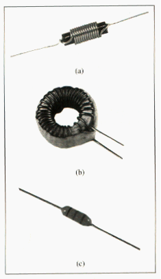
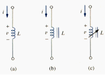
Like capacitors, commercially available inductors come in different values and types. Typical practical inductors have inductance values ranging from a few microhenrys ( H), as in communicatio0n systems, to ten of henrys (H) as in power systems. Inductors may be fixed or variable. The core may be made of iron, steel, plastic, or air. The terms coil and choke are also used for inductors. Common inductors are shown in [link]. The circuit symbols for inductors are shown in [link], following the passive sign convention.
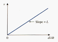
[link] is the voltage-current relationship for an inductor. [link] shows this relationship graphically for an inductor whose inductance is independent of current. Such an inductor is known as a linear inductor. For a nonlinear inductor, the plot of [link] will not be a straight line because its inductance varies with current. We will assume linear inductors in this textbook unless stated otherwise.
The current-voltage relationship is obtained from [link] as
Integrating gives
or
where is the total current for and . The idea of making is practical and reasonable, because there must be a time in the past when there was no current in the inductor.
The inductor is designed to store energy in its magnetic field. The energy stored can be obtained from [link]. The power delivered to the inductor is
The energy stored is
Since ,
We should note the following important properties of an inductor.
- Note from [link] that the voltage across an inductor is zero when the current is constant. Thus,
An inductor acts like a short circuit to dc.
2. An important property of the inductor is its opposition to the change in current flowing through it.
The current through an inductor cannot change instantaneously.
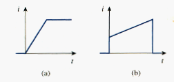
According to [link], a discontinuous change in the current through an inductor requires an infinite voltage, which is not physically possible. Thus, an inductor opposes an abrupt change in the current through it. For example, the current through an inductor may take the form shown in [link](a), whereas the inductor current cannot take the form shown in [link](b) in real-life situations due to the discontinuities. However, the voltage across an inductor can change abruptly.
3. Like the ideal capacitor, the ideal inductor does not dissipate energy. The energy stored in it can be retrieved at a later time. The inductor takes power from the circuit when storing energy and delivers power to the circuit when returning previously stored energy.
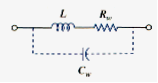
4. A practical, nonideal inductor has a significant resistive component, as shown in [link]. This is due to the fact that the inductor is made of a conducting material such as copper, which has some resistance. This resistance is called the winding resistance , and it appears in series with the inductance of the inductor. The presence of makes it both an energy storage device and an energy dissipation device. Since is usually very small, it is ignored in most cases. The nonideal inductor also has a winding capacitance due to the capacitive coupling between the conducting coils, is very small and can be ignored in most cases, except at high frequencies. We will assume ideal inductors in this book.
SERIES AND PARALELL INDUCTORS
Now that inductor has been added to our list of passive elements, it is necessary to extend the powerful tool of series-parallel combination. We need to know how to find the equivalent inductance of a series-connected or parallel-connected set of inductors found in practical circuits.
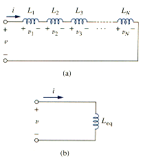
Consider a series connection of N inductors, as shown in [link](a), with the equivalent circuit shown in [link](b). The inductors have the same current through them. Applying KVL to the loop,
Substituting results in
where
Thus,
The equivalent inductance of series-connected inductor is the sum of the individual inductances.
Inductors in series are combined in exactly the same way as resistors in series.
We now consider a parallel connection of N inductors, as shown in [link](a), with the equivalent circuit in [link](b). The inductors have the same voltage across them. Using KCL,
But ; hence,
Where
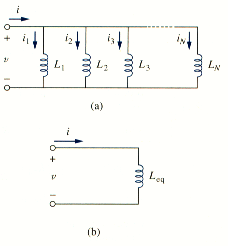
The initial current through at is expected by KCL to be the sum of the inductor currents at . Thus, according to [link],
According to [link]
The equivalent inductance of parallel inductors is the reciprocal of the sum of the reciprocals of the individual inductances.
Note that the inductors in parallel are combined in the same way as resistors in parallel.
For two inductors in parallel (N = 2), [link] becomes
or
It is appropriate at this point to summarize the most important characteristics of the three basic circuit elements we have studied. The summary is given in [link].
| Relation | Resistor (R) | Capacitor (C) | Inductor (L) |
| v-i: | v = iR | ||
| i-v: | i = v/R | ||
| p or w | |||
| Series: | Req = R1 + R2 | ||
| Parallel: | |||
| At dc: | Same | Open circuit | Short circuit |
| Circuit variable that cannot change abruptly: | Not applicable | v | i |
APPLICATIONS
Circuit elements such as resistors and capacitors are commercially available in either discrete form or integrated-circuit (IC) form. Unlike capacitors and resistors, inductors with appreciable inductance are difficult to produce on IC substrates. Therefore, inductors (coils) usually come in discrete form and tend to be more bulky and expensive. For this reason, inductors are not as versatile as capacitors and resistors, and they are more limited in applications. However, there are several applications in which inductors have no practical substitute. They are routinely used in relays, delays, sensing devices, pick-up heads, telephone circuits, radio and TV receivers, power supplies, electric motors, microphones, and loudspeakers, to mention a few.
Capacitors and inductors possess the following three special properties that make them very useful in electric circuits:
1. The capacity to store energy makes them useful as temporary voltage or current sources. Thus, they can be used for generating a large amount of current or voltage for a short period of time.
2. Capacitors oppose any abrupt change in voltage, while inductors oppose any abrupt change in current. This property makes inductors useful for spark or arc suppression and for converting pulsating dc voltage into elatedly smooth dc voltage.
3. Capacitors and inductors are frequency sensitive. This property makes them useful for frequency discrimination.
The first two properties are put to use in dc circuits, while the third one is taken advantage of in ac circuits. We will see how useful these properties are in later chapters. For now, consider three applications involving capacitors and op amp: integrator, differentiator.
Integrator
Important op amp circuits that use energy-storage elements include integrators and differentiators. These op amp circuits often involve resistors and capacitors; inductors (coils) tend to be more bulky and expensive.
The op amp integrator is used in numerous applications, especially in analog computers, to be discussed in section 3
An integrator is an op amp circuit whose output is proportional to the integral of the input signal.
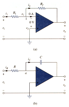
If the feedback resistor in the familiar inverting amplifier of [link](a) is replaced by a capacitor, we obtain an ideal integrator, as shown in [link](b). It is interesting that we can obtain a mathematical representation of integration this way. At node a in [link](b),
But
Substituting these in [link], we obtain
Integrating both sides gives
To ensure that , it is always necessary to discharge the integrator’s capacitor prior to the application of a signal. Assuming ,
Which shows that the circuit in [link](b) provides an output voltage proportional to the integral of the input. In practice, the op amp integrator requires a feedback resistor to reduce dc gain and prevent saturation. Care must be taken that the op amp operates within the linear range so that it does not saturate.
Differentiator
A differentiator is an op amp circuit whose output is proportional to the rate of change of the input signal.
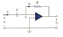
In [link](a), if the input resistor is replaced by a capacitor, the resulting circuit is a differentiator, shown in [link]. Applying KCL at node a,
But
Substituting these in [link] yields
Showing that the output is the derivative of the input. Differentiator circuits are electrically unstable because any electrical noise within the circuit is exaggerated by the differentiator. For this reason, the differentiator circuit in [link] is not as useful and popular as the integrator. It is seldom used in practice.
SUMMARY
- Current through a capacitor is directly proportional to the time rate of change of the voltage across it.
The current through a capacitor is zero unless the voltage is changing. Thus, a capacitor acts like an open circuit to a dc source.
- The voltage across a capacitor is directly proportional to the time integral of the current through it.
The voltage across a capacitor cannot change instantly.
- Capacitors in series and in parallel are combined in the same way as conductances.
- The voltage across an inductor is directly proportional to the time rate of change of the current through it.
The voltage across the inductor is zero unless the current is changing. Thus an inductor acts like a short circuit to a dc source.
- The current through an inductor is directly proportional to the time integral of the voltage across it.
The current through an inductor cannot change instantly.
- Inductors in series and in parallel are combined in the same way resistors in series and in parallel are combined.
- At any given time t, the energy stored in a capacitor is , while the energy stored in an inductor is .